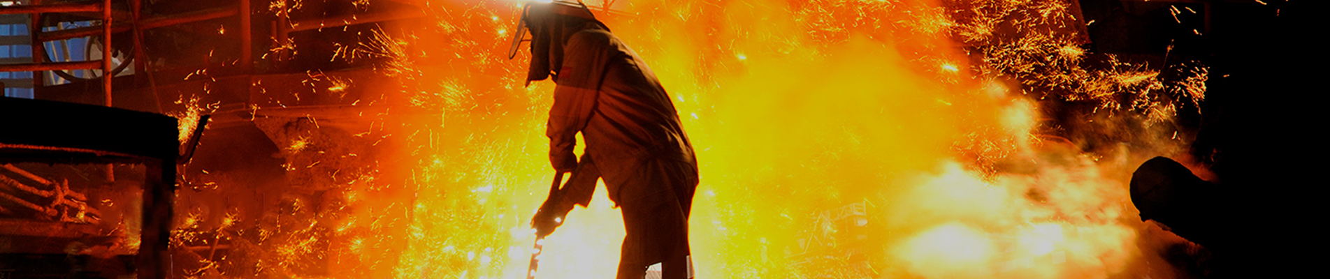
Aファブリック伸縮継手は、産業用ダクトに設置される柔軟な接続部材で、機器やダクトの各セクション間の動きを吸収します。硬質な鋼構造物に熱膨張、振動、または位置ずれを強制的に発生させるのではなく、柔軟なセクションがシステムの動きに合わせて変形します。
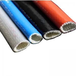
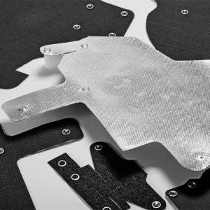
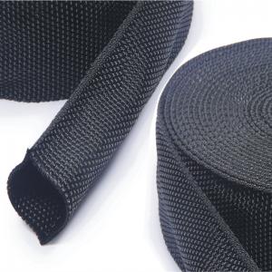
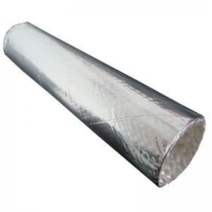
布製伸縮継手は、熱風、排気ガス、排煙ガス、その他の気体状プロセス媒体を輸送するシステムで一般的に使用されています。その柔軟な構成要素は、実際の運転条件に合わせて選択された織布、コーティング布、ガスシール膜、補強層、断熱材などで構成されます。
フレキシブル要素が非金属であるため、このタイプのジョイントは、非金属製伸縮継手または非金属製ファブリック伸縮継手。
カスタム工業デザインについては、以下を参照してください。BSTFLEX 非金属ファブリック伸縮継手。
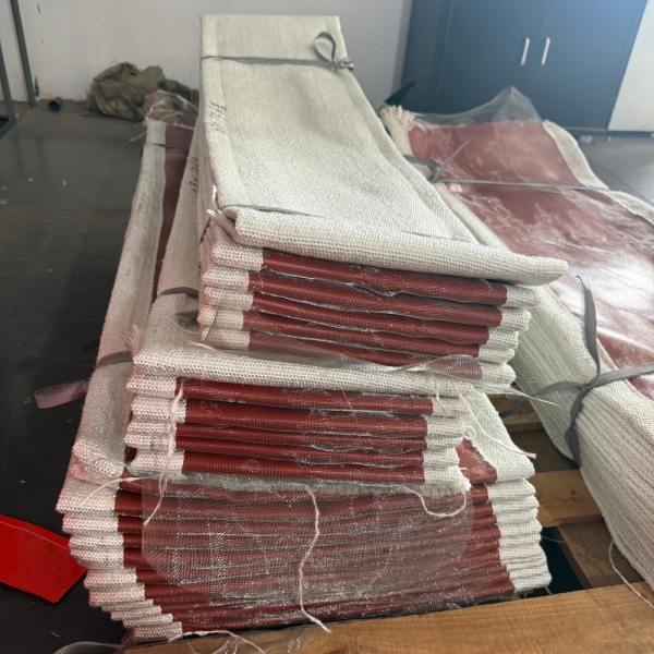
ファブリック製伸縮継手は、ダクトシステムの比較的剛性の高い2つの部分の間に配置される、設計された柔軟な部材です。その目的は、これらの部材間の必要な接続を維持しながら、制御された動きを可能にすることです。
工業用ダクトは、運転中に寸法が変化し続けることはほとんどありません。炉、ボイラー、排気システム、またはプロセスダクトが加熱されると、周囲の金属構造が膨張します。冷却されると、再び収縮します。ファンや回転機器によって振動が発生することもあり、設置時の公差によって隣接する部品間にわずかなずれが生じる場合もあります。
これらの動きが硬質ダクトを通して直接伝達されると、以下の箇所に追加の負荷がかかる可能性があります。
布製の接合部は、ダクト構造全体が剛性のある構造体として振る舞う必要なく、その動きの一部が発生する柔軟な領域を作り出す。
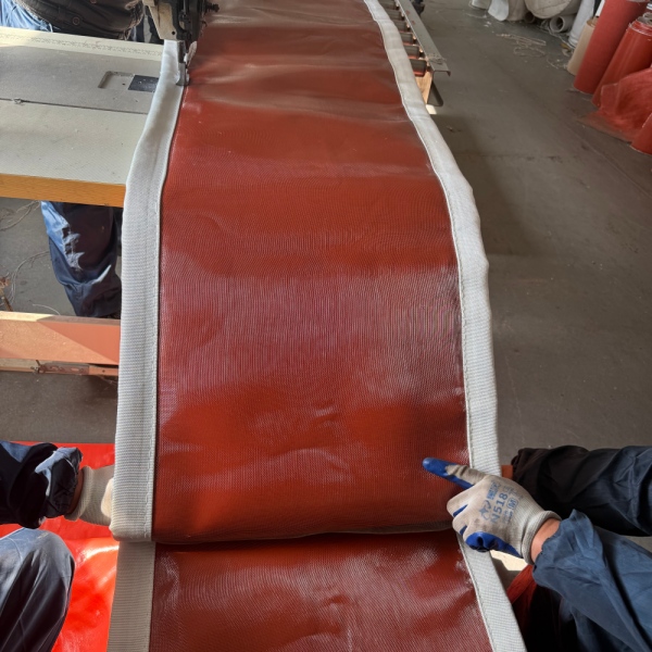
用語非金属製伸縮継手完全なアセンブリ内のすべてのコンポーネントではなく、柔軟な要素について説明する。
接合部周辺には、金属フレーム、クランプバー、ライナー、その他の金具が引き続き使用される場合があります。ただし、主要な柔軟な動きを担う部分は、成形された金属製ベローズではなく、布地、エラストマー、コーティングされた繊維、積層膜、またはこれらの材料の組み合わせで製造されます。
この区別は重要です。なぜなら、布製と金属製の伸縮継手は挙動が異なるからです。
金属製のベローズは、成形された金属の波状構造を曲げることで動きに対応します。布製の伸縮継手は、繊維または複合材製のベルトの柔軟性を利用して、ダクトの動きに合わせて形状を変化させます。
大型の工業用ダクト、特に比較的低圧の気体媒体を輸送するダクトの場合、この構造はコンパクトな設置スペースでかなりの可動性を実現できる。
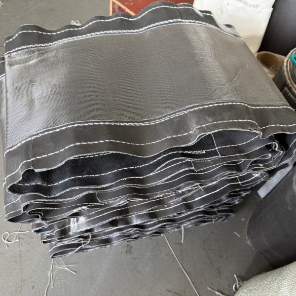
基本的な動作原理は単純明快だ。
制御された隙間によって隔てられた2つの高温ダクトを想像してみてください。柔軟な布製の部材がこの隙間をつなぎ、各ダクトセクションの周囲にしっかりと固定されます。
ダクトが加熱されて膨張すると、2つのセクション間の距離や位置関係が変化します。剛性のある接続部のようにその動きに抵抗するのではなく、柔軟なベルトは形状を変化させます。
設計によっては、関節は様々な種類の動きに対応できる。
軸方向圧縮は、2つのダクトセクション間の距離が中心線に沿って短くなるときに発生する。
これは、熱膨張によってダクトの一方の部分がもう一方の部分に向かって移動する際に頻繁に発生します。フレキシブルスパンは、距離の減少に対応するために、制御された方法で圧縮または折り畳まれます。
軸方向伸長は、これとは逆の状態です。接続部間の距離が長手方向に沿って増加します。
布地要素は、過度に引き伸ばされることなく拡張できるだけの十分な形状を備えている必要がある。
横方向の移動とは、一方のダクト接続部が他方のダクト接続部に対して横方向にずれる現象です。
これは、機器の移動、別の方向への熱膨張、または設置形状によって、単純な圧縮や伸長ではなくオフセットが生じるような大規模なダクトシステムにおいて特に重要です。
角度変化は、接続する2つの面が平行でなくなったときに発生します。
柔軟なベルトは周囲全体にわたって不均一に変形するため、片側が圧縮される一方で、別の部分が伸長する。
実際の産業システムは、必ずしも一方向にのみ動くとは限りません。軸方向、横方向、および角度方向の変位が同時に発生する可能性があります。
これは、ファブリックダクト伸縮継手これは、複雑なダクトレイアウトにおいて特に有効です。ジョイントの形状は、個々の変位を個別に扱うのではなく、想定される動きの組み合わせに基づいて設計できます。
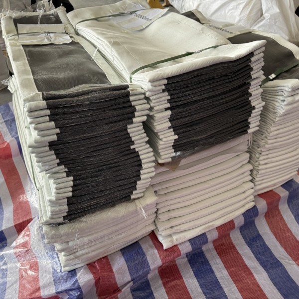
熱膨張は伸縮継手を設置する最もよく知られた理由ですが、唯一の理由ではありません。
完全な移動要件は、複数の運用条件によって生じる可能性がある。
| 原因 | システム内で何が起こるのか | 伸縮継手の役割 |
|---|---|---|
| 熱膨張 | 金属製のダクトは温度上昇に伴い膨張する。 | 寸法変化を制御可能 |
| 熱収縮 | ダクトは停止時または冷却時に収縮する | Allows the system to return toward its cold position |
| Fan Vibration | Mechanical vibration is transferred from rotating equipment | Provides a flexible connection between equipment and ducting |
| Misalignment | Connecting duct faces may not be perfectly aligned | Can accommodate specified offsets within the joint design |
| Structural Movement | Supports or equipment may move relative to each other | Provides a controlled flexible section |
| Operating Cycles | Repeated heating and cooling creates cyclic movement | Accommodates repeated dimensional changes when correctly designed |
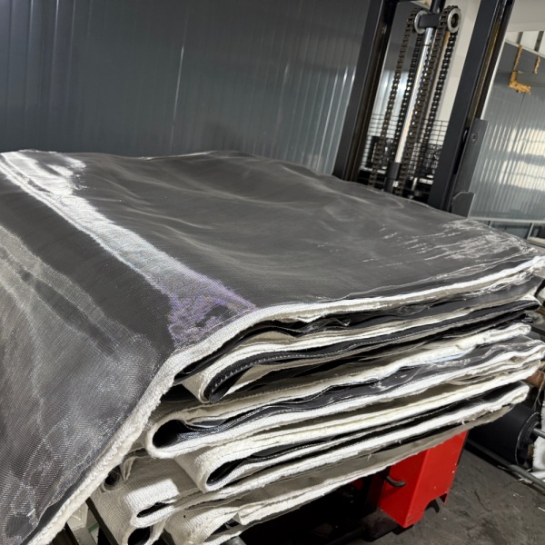
A fabric expansion joint should not be viewed simply as a piece of cloth connecting two ducts.
The flexible section is an engineered material system. Depending on service conditions, it may use a single flexible layer or several different layers, each selected for a specific function.
The outer layer forms part of the flexible envelope and may also provide resistance to weathering, environmental exposure or external mechanical conditions.
This layer helps contain the process gas. Its material must be compatible with the expected temperature, gas composition, moisture and chemical exposure.
Reinforcement provides mechanical support and dimensional stability to the flexible element. Fiberglass and other technical textile constructions are commonly considered depending on temperature and mechanical requirements.
High gas temperature does not necessarily mean every layer of an expansion joint should be exposed directly to that temperature.
An insulation package can reduce heat transfer from the process side toward temperature-sensitive sealing or outer layers.
Hot gas velocity, ash, dust or abrasive particles can damage an unprotected flexible surface. Some systems therefore require an internal liner, baffle or other protection to shield the joint from direct gas flow and particulate impact.
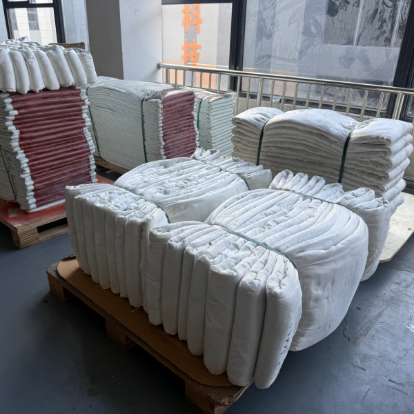
One material rarely provides every property required by a severe industrial application.
For example, a material with excellent temperature resistance may not provide the best gas sealing. A highly flexible sealing material may require reinforcement. A chemically resistant membrane may need insulation to keep its operating temperature within an acceptable range.
As a result, manyfabric expansion jointsuse a combination of materials rather than one fabric performing every function.
Typical material families include:
BSTFLEX also manufactures a broad range ofhigh temperature fabrics, allowing material construction to be evaluated according to thermal, chemical and mechanical requirements.
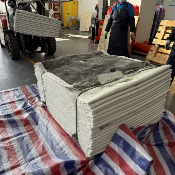
Fabric joints are mainly associated with industrial gas-handling and ducting systems rather than conventional high-pressure liquid piping.
Typical applications include the following.
Boilers, furnaces and combustion equipment can generate hot flue gases that must travel through large duct networks. These ducts experience significant dimensional change between ambient and operating temperatures.
Exhaust ducts connected to engines, industrial furnaces, thermal processing equipment or pollution-control systems may require movement compensation between hot equipment and downstream ducting.
Power plants use large gas-handling systems around boilers, fans, air-handling equipment and emission-control installations. Thermal growth and vibration can occur at multiple connection points.
Cement production combines heat, large duct dimensions, dust and continuous process operation. Flexible expansion sections may be required around kiln-related systems, fans and process ducts.
High-temperature furnaces, hot-air systems and exhaust ducts in steel and metal-processing plants can generate significant thermal movement.
Placing a flexible connection between rotating equipment and rigid ducting can help prevent all equipment movement from being transmitted directly into the surrounding duct structure.
Large ducting systems used with filtration, scrubber, flue-gas treatment and other air-pollution-control equipment often need flexible connections between process components.
Both products are intended to manage movement, but they should not be considered interchangeable simply because they share the term “expansion joint.”
| Characteristic | Fabric Expansion Joint | Metallic Bellows |
|---|---|---|
| Flexible Element | Fabric, coated textile or composite membrane | Formed metal bellows |
| Common Application | Large industrial ducts and gaseous-media systems | Industrial piping and engineered duct or process systems |
| Movement Method | Flexible belt changes geometry | Metal convolutions flex |
| Large Duct Sizes | Well suited to custom large cross-sections | Requires application-specific metallic design |
| Multidirectional Movement | Can accommodate several movement directions in one flexible section | Depends on bellows geometry and assembly design |
| Material System | Can combine several fabric, coating and insulation layers | Primarily determined by metallic alloy and bellows construction |
Pressure, temperature, process medium, movement, duct size and system design must all be considered before deciding which expansion joint technology is appropriate.
A flexible joint can help isolate vibration between connected components because its flexible element does not behave like a completely rigid metal duct section.
This is useful near fans, blowers and other equipment that produces mechanical vibration.
However, vibration should still be treated as an engineering input. Frequency, amplitude, equipment arrangement and joint geometry all influence performance. A fabric expansion joint should not be selected only because a system is described as “vibrating.”
There is no universal movement value that applies to every fabric expansion joint.
Movement capability depends on:
For this reason, axial, lateral and angular movements should be stated separately when specifying a custom expansion joint.
A request such as “50 mm total movement” is less useful than specifying how that movement occurs.
For example:
These values are examples of how movement information can be communicated, not standard ratings for every joint.
There is also no single temperature rating that defines all fabric expansion joints.
The allowable process temperature depends on the complete construction.
A high-temperature joint may be designed so that the process-side protection and insulation reduce the temperature reaching the gas-sealing membrane and external flexible layers.
Temperature selection should therefore consider:
This is why specifying only “high temperature fabric expansion joint” is insufficient for engineering selection.
A manufacturer needs more than the nominal duct dimensions to select a reliable construction.
The most useful project information includes:
| Design Information | Typical Details Required |
|---|---|
| Duct Geometry | Round, rectangular, square or special shape |
| Dimensions | Diameter or width and height |
| Face-to-Face Length | Available installation distance |
| Temperature | Normal and maximum process temperature |
| Pressure | Positive or negative operating and design pressure |
| Process Medium | Hot air, flue gas, exhaust gas or other process gas |
| Axial Movement | Compression and extension |
| Lateral Movement | Required transverse offset |
| Angular Movement | Required angular displacement |
| Chemical Conditions | Acidic, alkaline, moisture or other process exposure |
| Particulate Loading | Dust, ash or abrasive particles |
| Installation Environment | Indoor, outdoor, weather exposure or confined area |
Anon metallic expansion jointshould be considered when an industrial ducting system needs flexibility and the operating conditions are suitable for a fabric-based construction.
Typical reasons include:
The final decision should always be based on actual system conditions rather than the product name alone.
Some basic constructions can be standardized, but industrialfabric expansion jointsare frequently customized.
Two ducts with the same dimensions may require completely different expansion joints if they operate at different temperatures, carry different gases or experience different movements.
Important differences may include:
This is why drawings and operating data are particularly valuable when sourcing replacement or OEM fabric expansion joints.
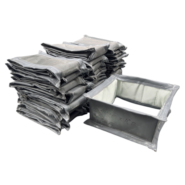
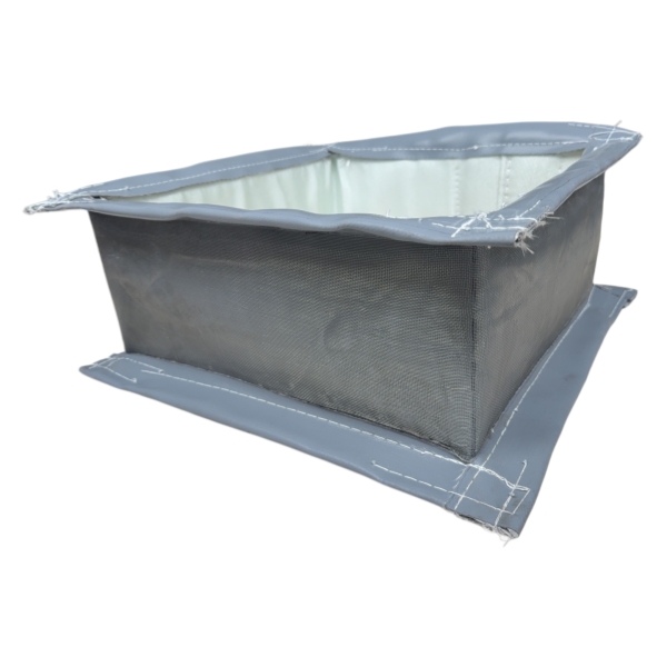
Rectangular joints are widely used on large industrial duct systems. Their corner sections require careful design because the flexible element does not deform identically along straight sides and corners.
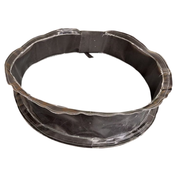
Round joints are used on circular ducting, fan connections and exhaust systems. The circumference provides a continuous attachment surface around the duct.
Square configurations are similar in principle to rectangular designs but may be required by specific duct or equipment layouts.
Transitions, non-standard dimensions and application-specific geometries can be manufactured when existing industrial equipment cannot accept a standard shape.
Expansion joint service life depends heavily on correct specification and installation.
Potential failure mechanisms include:
A damaged joint should therefore not automatically be replaced with an identical copy without understanding why the original unit failed.
For replacement projects, operating history can be as valuable as dimensional information.
In industrial ducting, the terms are often used for closely related products. A fabric expansion joint uses a flexible non-metallic fabric or composite element, so it falls within the broader non-metallic expansion joint category. The exact terminology varies by industry and construction.
It provides a flexible connection between sections of industrial ductwork so thermal expansion, contraction, lateral displacement, angular movement, vibration and specified misalignment can be accommodated without making the connection completely rigid.
Typical locations include industrial exhaust ducts, flue-gas systems, furnace and boiler ductwork, fan connections, cement plants, power-generation equipment, steel-processing facilities and air-pollution-control systems.
Yes. Depending on the design, they can accommodate axial compression, axial extension, lateral movement, angular movement and combinations of these movements.
No. Fiberglass is an important reinforcement and high-temperature textile, but complete expansion joints may combine coated fiberglass, PTFE-coated fabric, silicone-coated textiles, silica fabrics, insulation and other materials according to operating conditions.
はい、材料システム全体が実際のプロセス温度とガス条件に合わせて設計されている場合に限ります。高温用途では、多くの場合、複数の機能層と、高温ガス流と柔軟なシール要素との間の適切な保護が必要となります。
自動的には変更できません。布製と金属製の伸縮継手は、圧力、動き、温度、機械的特性が異なります。伸縮継手の技術を変更する前に、システムの状況を評価する必要があります。
有用な情報としては、ダクトの幅と高さまたは直径、面間長さ、フランジ寸法、ボルト配置、ジョイント形状、および設置可能なスペースなどが挙げられます。動作温度、圧力、流体、および動作要件も不可欠です。
BSTFLEXは開発していますファブリック伸縮継手工業用ダクト、排気、温風、排ガス用途向け。円形、長方形、正方形、および非標準的なダクト形状に対応可能で、温度、圧力、プロセス媒体、動き、設置条件に応じて材料システムを選定できます。
新しいシステムを開発する場合、または既存のジョイントを交換する場合は、BSTFLEX 非金属ファブリック伸縮継手製品ページでは、利用可能な構造オプションとカスタマイズオプションをご確認いただけます。
技術評価のために、ダクトの寸法、通常温度と最高温度、運転圧力、プロセス媒体、軸方向の動き、横方向の動き、設置長さ、数量、および入手可能な図面をお送りください。

 English
 français
 Deutsch
 русский
 italiano
 español
 português
 Nederlands
 العربية
 한국의
한국의 Türkçe
 Polski
 Tiếng Việt
 slovenský
 Indonesia